
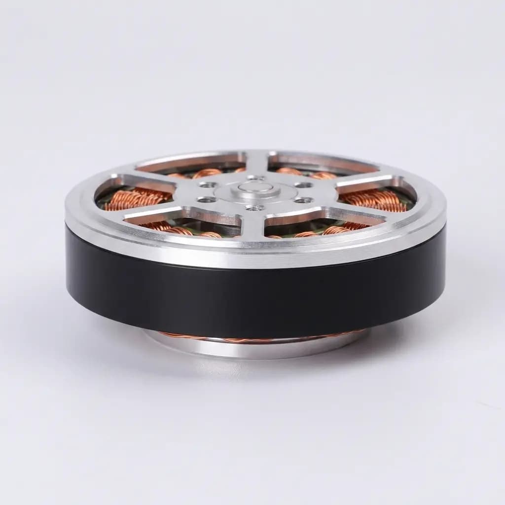
Check peak load first
Compare the joint moment from your intended trajectory with a supplier torque-speed curve at the same speed and bus voltage.
Estimate a static-equivalent joint moment from per-joint load assumptions, then compare it with the 105 Nm page target. This screen does not select or certify an actuator.
Target class only · request a signed model datasheet
Request verified torque data58.9 Nm
Example valuesBelow the 105 Nm page target in this simplified estimate. This does not establish actuator suitability.
46.1 Nm below the page target
Compare the joint moment from your intended trajectory with a supplier torque-speed curve at the same speed and bus voltage.
Peak torque alone does not establish continuous capability. Ask for the duty cycle, test ambient, mounting fixture, and temperature limits behind the continuous rating.
Verify mass, dimensions, bearings, sensors, bus protocol, and connector pinout against the robot interface before procurement.
The calculator uses effective mass at one joint, gravity, a perpendicular moment arm, and your selected multiplier. It is a screening calculation; it does not solve robot kinematics or dynamics, estimate motor current, or validate thermal performance.
M = m × 9.81 × r × k
Early shortlist discussions when a per-joint effective mass, lever arm, and load multiplier are available.
Final actuator selection, safety approval, gait prediction, jump landing analysis, continuous torque sizing, or gearbox life approval. Use multibody simulation and measured data for those decisions.
The page identifies a 105 Nm target class. It does not include a revision-controlled datasheet for a specific orderable configuration.
| Decision item | Published here | Confirm before design freeze |
|---|---|---|
| Torque class | 105 Nm target class | Peak torque definition, speed, current, and pulse duration |
| Thermal envelope | Not specified | Continuous torque, duty cycle, ambient, mounting, and temperature limit |
| Mechanical package | Illustrative image only | Mass, envelope drawing, shaft/flange, bearings, and allowable loads |
| Electrical and control | Not specified | Voltage range, current limits, speed curve, encoder, bus, firmware, and connectors |
| Life and environment | Not specified | Gear life evidence, shock limits, ingress rating, lubrication, and operating temperature |
These are qualitative design prompts. Actual friction, stiffness, backlash, efficiency, and impact limits depend on the chosen hardware and test conditions.
| Approach | Potential fit | Ask / validate |
|---|---|---|
| Low-ratio QDD | Dynamic joints where force interaction and backdrivability matter | Backdrive torque, reduction, motor limits, heat path, and peak duty |
| High-ratio geared joint | Applications prioritizing compact torque multiplication or position holding | Friction, output stiffness, backlash, impact load, and service life |
| Series-elastic joint | Applications that can use intentional compliance for force interaction | Spring travel, resonance, bandwidth, packaging, and fatigue life |
The examples below are arithmetic demonstrations of the stated formula, not measured robot cases or validated product matches.
8 kg · 0.20 m · 1.5×
23.5 Nm
Below the page target in this simplified screen.
12 kg · 0.25 m · 2.0×
58.9 Nm
Requires trajectory and thermal checks.
20 kg · 0.30 m · 2.5×
147.2 Nm
Above the page target; review mechanism and actuator class.
A moment estimate cannot establish continuous operation. Request peak and continuous torque-speed curves plus thermal test setup, duty cycle, and derating rules.
Side loads, shocks, bearing span, mounting stiffness, and service conditions affect the gear train. Request drawings, allowable loads, and life or endurance evidence for the intended spectrum.
Encoder placement and motor-current torque estimates do not by themselves establish output accuracy or a safety-rated function. Define the required torque feedback and fault response.
Custom windings, housings, sensors, and connectors can change price, schedule, qualification effort, and future interchangeability. Get the quoted configuration and change-control terms in writing.
This page does not establish whether 105 Nm is a peak, stall, or continuous rating, nor its duration or speed. Request the configuration-specific torque-speed and thermal data.
No. It estimates a simplified joint moment. Final selection also needs trajectory torque and speed, RMS duty, electrical limits, mechanical loads, and thermal validation.
It is the mass whose weight creates the modeled moment at this joint. Estimate it from the joint load case; robot total mass is not automatically the value for one actuator.
It only scales the static-equivalent moment. It does not predict landing force, impact duration, contact geometry, or gearbox shock load. Use simulation or measurement for those cases.
The public page does not confirm the bill of materials for a specific configuration. Ask whether the quote includes motor, reducer, sensors, drive electronics, cables, and firmware.
Share the joint load and speed profile, duty cycle, environment, mechanical envelope, bus and sensing requirements, quantities, and validation needs. Request a revision-controlled response.
Send the application and load profile with your RFQ. Ask the supplier to identify which quoted configuration each drawing, curve, and test result covers.
Inquiry Email
Include robot type, joint location, torque/speed/voltage targets, quantity, and destination.
Instant Chat
+86 18857971991
Send QDD actuator specs, STEP files, or actuator references for engineering review.
The formula above is shown explicitly so the estimate can be reproduced. The research reference below supports the general design trade-off for dynamic legged robots; it does not validate this page's 105 Nm target or any specific supplier configuration.
Wensing et al., IEEE Transactions on Robotics, 2017. The study discusses high-bandwidth force interaction and impact mitigation in its tested legged-robot system. Its results are architecture evidence, not a specification for this module.
Page and source reviewed September 30, 2026. Product-specific public datasheet: not linked on this page; request the signed revision and supporting test reports from the supplier.