LogoQDD Actuator
Start inquiry
LogoQDD Actuator
WhatsApp
LogoQDD Actuator

Shenzhen and Dongguan QDD actuator factory network supporting robot joint selection, prototype validation, sample review, and B2B export delivery.

Inquiry Email

[email protected]

Email app

Include robot type, joint location, torque/speed/voltage targets, quantity, and destination.

Instant Chat

+86 18857971991

Chat on WhatsApp

Send QDD actuator specs, STEP files, or actuator references for engineering review.

Products
  • QDD Robot Actuators
  • Backdrivable Actuators
  • Hollow-Shaft QDD Actuators
  • All Products
Solutions
  • Quadruped Robots
  • Humanoid Lower Limbs
  • Exoskeletons
  • All Applications
OEM Capabilities
  • Custom QDD Actuator
  • Prototype to Production
  • Private-Label Actuators
  • OEM Hub
Engineering
  • QDD Explained
  • QDD vs Harmonic Drive
  • Thermal Sizing
  • All Engineering Resources
  • QDD Actuator Blog
  • Buyer Resources
Resources
  • CAD / Datasheet Library
  • Developer Support
  • Compliance Documents
  • About
  • Manufacturing Network
  • Contact / RFQ
  • Privacy Policy
  • Cookie Policy
  • Terms of Service
© 2026 QDD Actuator. All Rights Reserved.|Direct QDD actuator RFQ: [email protected] | WhatsApp +86 18857971991 | LinkedIn contact.
Backed by Linkup Ai Co., Ltd. Manufacturing delivered by the Advanced Manufacturing Division of Linkup Precision.|Legal entity: Linkup Ai Co., Ltd.
← Back to Products

Hollow-Shaft QDD Actuators

QDD actuator layouts with hollow or pass-through routing concepts for compact robot joints that need clean cable, hose, or sensor routing.

Target Buyer:Best for robot mechanical teams constrained by cable routing, joint envelope, and serviceability.
Hollow rotary actuator module for cable-routing and compact joint review

Capability Highlights

  • Hollow routing review for joint cables and sensor harnesses
  • Compact coaxial packaging for hips, knees, ankles, and arm joints
  • Custom shaft, flange, bearing, and connector layouts for OEM builds

Typical Applications

  • Humanoid hip and ankle joints
  • Quadruped leg modules with protected cable routing
  • Mobile manipulator and research robot joints

Engineering Focus

  • Through-hole diameter, bend radius, and connector clearance
  • Shaft/flange strength, bearing layout, and radial load path
  • Sealing, harness exit direction, and assembly/service access

Buyer Decision Summary

A buyer should leave this page with a shortlist decision: whether this actuator family deserves a sample review, what must be measured first, and which constraints must be fixed before price comparison.

Best Evidence

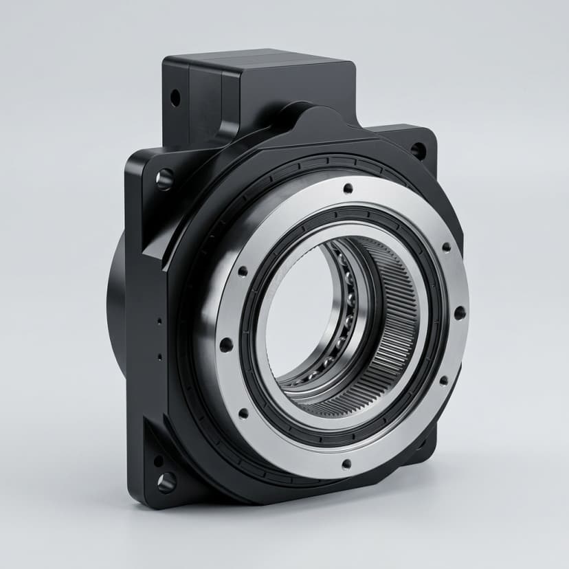
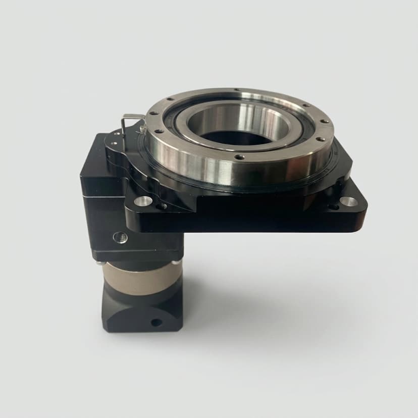
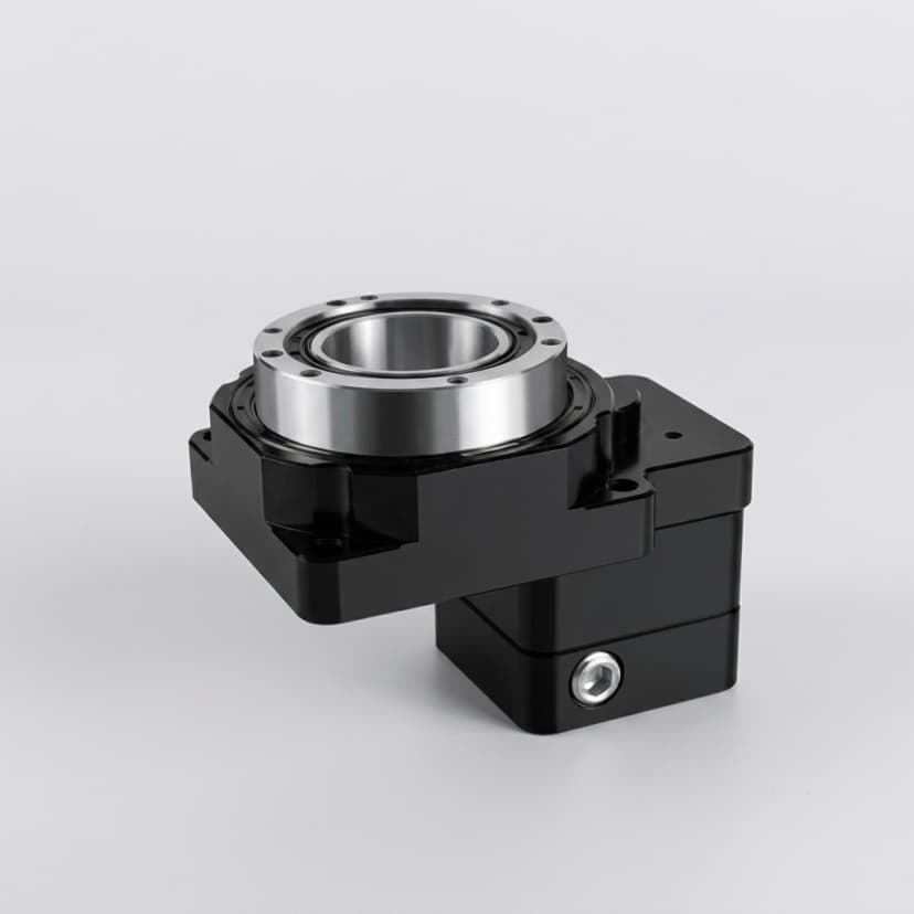
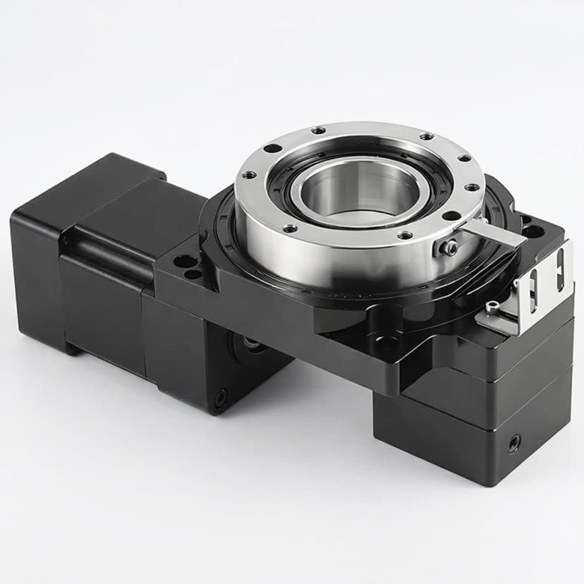
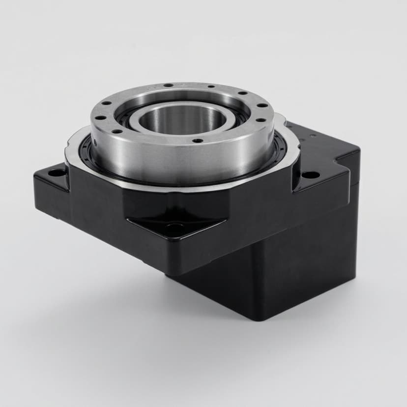
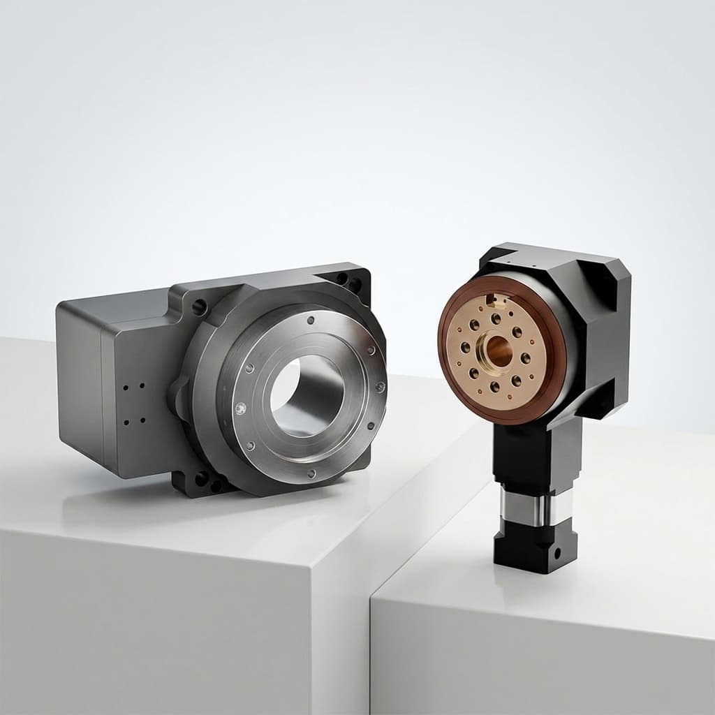
Start with pass-through envelope and connect it to the real robot duty cycle instead of reviewing catalog values alone.

Primary Risk

Cable routing is solved after the actuator is selected

Next Buyer Action

Prepare required hollow diameter or cable bundle dimensions plus validation targets before requesting samples or commercial terms.

How to Evaluate This Actuator Family

Use this page to turn a product family into a shortlist decision. The useful comparison is not one headline torque number; it is how the actuator behaves inside the real robot joint.

Pass-through envelope

10–25 mm bore diameter depending on actuator class

Determines whether power, signal, brake, or sensor harnesses can route through the joint.

Bearing load path

Radial 2–8 kN, axial 1–5 kN depending on output bearing class

Prevents the hollow-shaft layout from weakening the output support.

Assembly access

Cable exit at 0°, 90°, or 180° relative to output flange

Affects field service, harness replacement, and repeatable production assembly.

Sample Validation Plan

Before a batch decision, buyers should define the evidence expected from sample review and internal testing.

Signal to CheckReview BasisEvidence to Ask For
Pass-through envelope10–25 mm bore diameter depending on actuator classDefine hollow diameter, connector direction, and bend radius before mechanical freeze.
Bearing load pathRadial 2–8 kN, axial 1–5 kN depending on output bearing classReview load path, wall thickness, bearing span, and output flange geometry together.
Assembly accessCable exit at 0°, 90°, or 180° relative to output flangeDefine hollow diameter, connector direction, and bend radius before mechanical freeze.

Acceptance Thresholds to Define

Define measurable pass/fail thresholds before the sample arrives. This prevents a subjective review where one team checks torque, another checks packaging, and nobody records whether the actuator can move toward pilot build.

  • Pass-through envelope: Determines whether power, signal, brake, or sensor harnesses can route through the joint.
  • Bearing load path: Prevents the hollow-shaft layout from weakening the output support.
  • Assembly access: Affects field service, harness replacement, and repeatable production assembly.

When This Family May Not Fit

A QDD actuator family is valuable only when the application needs its trade-offs. The same module can be a poor fit when the surrounding joint requirements point in a different direction.

  • Cable routing is solved after the actuator is selected: Define hollow diameter, connector direction, and bend radius before mechanical freeze.
  • A large hollow shaft reduces stiffness or bearing margin: Review load path, wall thickness, bearing span, and output flange geometry together.

Buyer Inputs That Improve the First Reply

A complete first inquiry shortens review loops because engineering can separate fixed constraints from adjustable actuator choices.

Fixed Constraints

  • Required hollow diameter or cable bundle dimensions
  • Joint envelope, shaft/flange drawing, and load direction
  • Connector type, cable exit direction, and service access needs

Review Targets

  • Torque-speed-voltage target and thermal duty cycle
  • Prototype quantity and sample validation plan

Key Evaluation Matrix

MetricTypical RangeWhy It Matters
Pass-through envelope10–25 mm bore diameter depending on actuator classDetermines whether power, signal, brake, or sensor harnesses can route through the joint.
Bearing load pathRadial 2–8 kN, axial 1–5 kN depending on output bearing classPrevents the hollow-shaft layout from weakening the output support.
Assembly accessCable exit at 0°, 90°, or 180° relative to output flangeAffects field service, harness replacement, and repeatable production assembly.

Engineering Documents by RFQ

Document packages are shared after the actuator family, joint envelope, and program context are clear. Ask for available datasheets, drawings, CAD files, torque-speed notes, compliance records, or test reports during RFQ review.

DocumentStatusRFQ Input Needed
Datasheet PDFAvailable by actuator class reviewTorque, speed, voltage, and quantity target
2D drawingAvailable by mechanical envelope reviewShaft, flange, bolt pattern, and connector constraints
3D CAD / STEP / IGESShared when applicable after RFQ contextJoint envelope, mounting direction, and confidentiality needs
Torque-speed / thermal envelopeProgram-dependent reviewDuty cycle, ambient temperature, current limit, and mounting heat path
Compliance or test reportsRequestable per program when availableDestination market and required document list
How to Request CAD / DatasheetsCompliance Document Scope

RFQ Checklist

  1. Required hollow diameter or cable bundle dimensions
  2. Joint envelope, shaft/flange drawing, and load direction
  3. Connector type, cable exit direction, and service access needs
  4. Torque-speed-voltage target and thermal duty cycle
  5. Prototype quantity and sample validation plan

Risk Controls

  • Cable routing is solved after the actuator is selected: Define hollow diameter, connector direction, and bend radius before mechanical freeze.
  • A large hollow shaft reduces stiffness or bearing margin: Review load path, wall thickness, bearing span, and output flange geometry together.

Product Gallery

Hollow-shaft rotary actuator module for robot wiring path evaluation
Hollow gear rotary actuator module for shaft and harness routing review
Hollow servo rotary actuator module for compact integration layouts
Hollow rotary actuator reference for through-bore robot joint packaging
Hollow servo actuator module for cable-routing and mounting discussion
Hollow gear actuator module for robot joint packaging comparison
Hollow rotary servo gear actuator module for OEM integration review

Buyer FAQ

Can every QDD actuator be made hollow-shaft?

No. Hollow routing depends on torque class, diameter, bearing layout, motor geometry, and connector requirements.

Can you review our joint envelope before sample selection?

Yes. Send drawings, STEP references, cable bundle data, and load assumptions for engineering review.

Related Resources

  • Humanoid Lower-Limb Applications
  • Custom QDD Actuator OEM
  • Contact / RFQ

Inquiry Email

[email protected]

Email app

Include robot type, joint location, torque/speed/voltage targets, quantity, and destination.

Instant Chat

+86 18857971991

Chat on WhatsApp

Send QDD actuator specs, STEP files, or actuator references for engineering review.