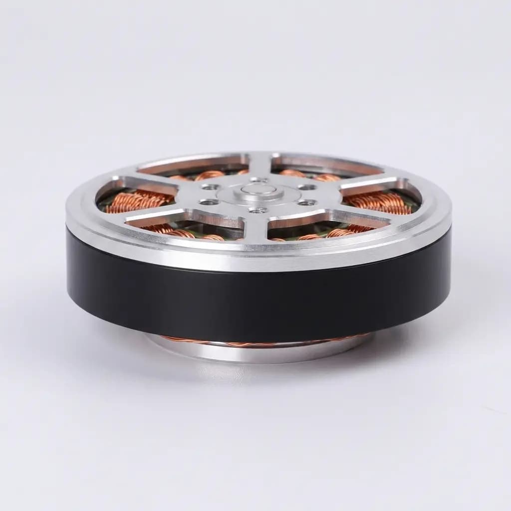
High-torque-density 105Nm quasi-direct-drive (QDD) actuator module with low reflected inertia, high impact resistance, and active force control for humanoid robot joints and legged platforms.
Hybrid Mode105 Nm peak screening with interactive load match and RFQ caveats.
Page last updated July 28, 2026. Source review combines supplier baseline data with public QDD architecture references.
Simulate humanoids and quadruped leg kinematics to calculate peak load matches.
1. Input Robot Configurations
Robot Geometry Layout
Target Joint Location
35 kg
15 kg150 kg
0.3 m
0.15 m0.80 m
locomotion gait dynamics
Dynamic factors scale the gravity load vector to account for inertia during acceleration.
Driver DC Bus Voltage
2. Calculation & Safety Match
Peak Joint Torque Required103 Nm
Optimal Match
Safety Factor Matrix1.02x (105Nm limit)
Reflected Inertia (J_ref)0.0416 kg·m²
Backdrive Impedance< 0.58 Nm
Thermal Headroom2% remaining
Method assumptions
Peak torque = mass x 9.81 x lever x dynamic factor x joint coefficient / support-leg count.
Support-leg count defaults to 2 for humanoids and 4 for quadrupeds; single-leg stance, stairs, and jumps need multibody simulation.
105 Nm is a peak-pulse screen. Continuous gait acceptance should use the 35 Nm RMS thermal baseline and buyer-specific heat-sink design.
Actuator Sizing Verdict:
Good first-pass match under the selected load assumptions. Validate trajectory peaks, frame heat sinking, and software current limits before prototype release.
Treat these figures as RFQ screening targets. Public sources support the QDD design rationale, while QDD-105-specific values should be confirmed with a signed datasheet, CAD package, thermal log, and dynamometer report before design freeze.
Torque Density
42.8 Nm/kg
Supplier baseline peak density using the 105 Nm pulse target and 2.45 kg module mass.
Reflected Inertia
0.052 kg·m²
Low 8:1 ratio screen for mechanical transparency and impact backdrivability.
Thermal Continuous
35 Nm RMS
Continuous-screening baseline for gait RMS torque with frame heat sinking.
Commutation Bandwidth
20 kHz FOC
Driver target for current control; confirm firmware loop rates by quoted batch.
Visual Evidence & Assembly
Engineering Diagrams & Mathematical Models
Review the mechanical assembly, speed boundaries, and backdrivability energy absorption path of our 105Nm actuator module.
Review the factory calibration tolerances, housing materials thermal dissipation, and planetary efficiency under load.
Procurement note: Treat actuator-specific limits below as supplier screening targets until the quoted batch is matched to a signed datasheet, inspection report, and thermal duty-cycle log.
Metallurgical Impact: High case depth (0.6–0.9 mm) combined with root grinding minimizes dynamic fatigue and root shear under peak torque spikes (105 Nm).
Tribology & Precision Joint Lubricants
Lubricant Brand
Base Oil & Thickener
Operating Temp
NLGI Class & Advantage
Kyodo Yushi Molywhite RE No. 00
Synthetic Hydrocarbon (PAO) + Lithium soap
-40°C to +130°C
Semi-fluid (NLGI 00) - Extremely high load, anti-fretting under micro-oscillations
NLGI 2 (Standard Grease) - Superior water-washout resistance, good for outdoor field quadrupeds
Tribology Note: Semi-fluid NLGI 00 grease prevents channeling effects in compact planetary systems, ensuring 100% wet lubrication on sun-and-planet gear tooth meshes at startup.
Application Screening
Humanoid & Legged Robotics Sizing Scenarios
Use these modeled scenarios to shape an RFQ and validation plan. They are not published customer deployments or third-party lab reports.
01
35 kg Humanoid Knee / Hip Pitch Screening Scenario
Premise: A biped humanoid in the public mid-size class needs a first-pass knee or hip-pitch actuator shortlist before detailed multibody simulation.
Process: Model the joint with 35 kg total robot mass, 0.35-0.40 m lever length, 2.0-3.2G dynamic factor, and 48 V bus assumptions, then compare peak demand against 105 Nm pulse torque and 35 Nm RMS thermal baseline.
Screening Outcome: Screening outcome: the QDD-105 class can be shortlisted when the duty-cycle RMS torque stays below the continuous baseline. Landing, stair, and jump cases still require prototype thermal logs and gearbox shock validation.
02
50 kg Quadruped Hip / Knee Outdoor Duty Screening
Premise: An inspection quadruped must choose between a compact 105 Nm QDD module and a heavier actuator for rough outdoor gait cycles.
Process: Use the calculator with quadruped load sharing, 0.30-0.45 m limb geometry, 2.0G regular gait factors, and a chassis heat-sink assumption, then check whether the RMS joint torque remains near the 35 Nm continuous screen.
Screening Outcome: Screening outcome: the actuator is plausible for prototype review when the frame can remove heat from the stator housing. Desert-temperature or sealed-leg designs need derating data before procurement.
Premise: A lower-limb exoskeleton needs high backdrivability and a low perceived resistance target before safety testing with users.
Process: Evaluate the 8:1 planetary configuration as a low-impedance candidate, then specify an output-side torque sensor or dynamometer validation plan for patient-facing risk controls.
Screening Outcome: Screening outcome: low-ratio QDD architecture is worth a prototype test, but comfort and safety claims must come from the buyer’s medical-device validation protocol, not from this calculator.
04
Collaborative Arm Torque-Estimation Architecture Screening
Premise: A cobot shoulder or base joint needs a compact, backdrivable torque source while keeping the collision-detection architecture auditable.
Process: Compare motor-current torque estimation against an architecture with a dedicated output torque sensor, then define the required response-time test before selecting the integrated driver option.
Screening Outcome: Screening outcome: integrated current-based estimation can reduce wiring and BOM complexity, but safety-rated collision detection still needs application-specific validation and documented fault handling.
FAQ & Support
Buyer Technical Q&A & Support Reference
Technical answers regarding mechanical backdrivability, electrical bus protocols, and thermal sizing tolerances.
Why is low reflected inertia critical for legged/humanoid robots?
Reflected inertia is proportional to the square of the gear reduction ratio. In high-ratio harmonic systems (e.g., 100:1), motor inertia is multiplied by 10,000, creating a highly rigid joint that transfers external impact shocks directly to the gears, causing tooth breakage. In our 105Nm QDD actuator (8:1 planetary ratio), motor inertia is only multiplied by 64, allowing the joint to rotate backward (backdrive) and absorb shock forces mechanically.
What gear steel grade is used in the planetary reducer of the 105Nm module?
We use high-purity aerospace alloy steel (18CrNiMo7-6) with precise carburizing and tooth profiling modification. The tooth root thickness is increased with a 22.5° pressure angle, doubling bending fatigue strength under impact loading compared to standard industrial gears.
How does the 105Nm QDD handle backlash degradation over time?
The standard design target uses planetary preload, hardened gear surfaces, and dual-encoder compensation to keep initial backlash in the 3-5 arcmin class. Treat long-term backlash drift as an RFQ validation item: request the supplier endurance log for your torque spectrum before locking the joint design.
Is the 15mm hollow shaft bore customizable?
Yes, the standard version has a 15mm clear through-bore. We can customize this up to 20mm for route-heavy joints, but this reduces internal bearing dimensions. Contact engineering to review radial and axial load capacity changes.
Can this QDD actuator operate reliably in force control without an external torque sensor?
It can be screened for current-based torque estimation because the low-ratio planetary stage keeps friction and reflected inertia lower than high-ratio gearboxes. For safety-rated force control, validate the current-to-output-torque model with a dynamometer or add an output torque sensor.
What is the purpose of the dual-absolute encoder setup?
The motor-side encoder (19-bit magnetic) operates high-speed FOC current commutation. The output load-side encoder (19-bit absolute) measures actual joint angles. This allows the driver to correct for planetary backlash, tooth deflection under load, and mechanical joint compliance in real-time.
What communication protocols does the integrated driver support?
The integrated driver supports EtherCAT (CoE, up to 2.0 kHz loop rate) and CAN-FD (up to 1.0 kHz loop rate) out-of-the-box. RS-485 is available for simple non-dynamic auxiliary axes.
How do you handle torque ripple (cogging torque) at low speeds?
By using fractional-slot concentrated windings and stator skewing combined with active harmonic current injection (5th and 7th order slot harmonics compensation) in the driver firmware. This keeps torque ripple under 1.4% of peak ratings.
How does high winding temperature affect joint performance?
High winding temperatures increase stator copper resistance. From 20°C to 110°C, the motor torque constant (Kt) drops by roughly 11%. The driver firmware continuously estimates winding temperature and compensates current gains to maintain torque output stability.
What is the thermal shutdown limit and safety threshold?
Winding temperature safety warning triggers at 95°C. At 110°C, the driver initiates automatic linear current derating (4% torque reduction per °C). At 125°C, bridge MOSFETs enter over-temperature shutdown to protect coil insulation from degradation.
How do I calculate the thermal headroom for my gait duty cycles?
Calculate the Root Mean Square (RMS) torque of your movement loop. As long as the RMS torque is within the continuous thermal limit of 35 Nm (mounted to a standard aluminum heatsink frame at 25°C ambient), the joint temperature will stabilize below 80°C.
Does the actuator support liquid cooling paths?
We offer an optional liquid cooling jacket housing customization (OEM) for heavy payload humanoids. Under liquid cooling, the continuous torque threshold increases from 35 Nm to 52 Nm due to accelerated heat dissipation.
How does winding temperature rise affect the motor torque constant (Kt) and how is it compensated?
As stator coil temperature rises from 20°C to 110°C, the torque constant (Kt) drops by ~11.5% due to the increased resistance of the copper wire and the temperature-dependent reduction in magnetic flux density of the NdFeB magnets. To mitigate this torque fade, the integrated FOC driver executes real-time compensation via a software-based thermal model. By calculating winding resistance using phase current integration and correcting the FOC q-axis current gain dynamically, torque linearity is maintained within ±1.5%.
Which FOC controller chip architecture drives the integrated inverter, and what is the current control bandwidth?
The integrated driver is specified around a Cortex-M4-class FOC controller with a 20 kHz current-loop target. Exact MCU, firmware loop rates, and disturbance-response timing should be confirmed from the signed BOM and firmware release notes for the batch quoted.
What is the backlash drift expectation under continuous humanoid walking cycles?
Initial factory-cleared backlash is targeted in the 3-5 arcmin range. Drift depends on torque spectrum, lubrication, shock loading, temperature, and sealing, so continuous-walking endurance should be accepted only against a buyer-specific test profile and inspection interval.
What happens if the absolute encoder loses magnetic sync or experiences strong interference?
The dual-encoder safety architecture allows the driver to fall back to the motor-side incremental/hall states for emergency commutation, immediately throwing a safety fault to the master EtherCAT/CAN controller. This prevents dangerous high-speed runaway and allows a controlled compliant stop.
How does IP rating affect thermal performance and continuous torque limit?
There is a strict trade-off between sealing (IP65/IP67) and thermal dissipation. A fully sealed IP67 housing prevents ingress but traps stator heat, which can derate the continuous 35Nm RMS limit by up to 25% (down to ~26Nm) unless active liquid cooling or massive chassis heat-sinking is used. IP54 vented designs allow better air cooling but risk dust and moisture ingress.
What is the MTBF (Mean Time Between Failures) for the planetary reducer?
Under nominal load (35Nm continuous, occasional 105Nm peaks), the planetary gears target a >10,000 hour L10h lifecycle. However, if exposed to sustained shock impacts without sufficient regenerative backdrivability, or if lubricant channeling occurs at low temperatures (-20°C), the MTBF can drop significantly. Always test the specific gait profile.
Engineering Sizing Disclaimer & Safety Warning:The output joint calculations and torque estimates generated by this simulator are for initial design evaluation and baseline scoping only. Actual dynamic joint behavior will vary depending on payload fluctuations, walking gait trajectory profiles, mechanical linkage deformation, and ambient thermal conditions. Data extrapolations for loads above 120Nm are unverified (supplier-confirmed data required). Robotics R&D teams must perform dynamic multibody physical simulations and physical prototype testing under thermal load before finalized volume design sign-off.
RFQ Procurement Checklist & Lead Time Sizing
Include the following requirements in your RFQ email to receive CAD files, pricing, and sample availability after engineering review.
Required Procurement Details
Dynamic Load Cycle: Target acceleration profiles, continuous payload mass, and leg layout geometry STEP reference.
Send QDD actuator specs, STEP files, or actuator references for engineering review.
Related Decision Paths
Continue the 105Nm QDD Actuator Review
Use these same-site resources to compare QDD architecture, humanoid lower-limb fit, low-ratio planetary trade-offs, and OEM customization requirements before sending the RFQ.
This hybrid page combines public QDD design references, supplier baseline values, and standards-based risk framing. Public sources do not independently certify every QDD-105 value on this page; request signed datasheets and test reports during RFQ. Source review date: July 28, 2026.
Ref [01]
QDD-105 supplier engineering baseline and RFQ datasheet request
Reviewed September 26, 2026 · Supplier baseline; request signed datasheet and test logs
Scope: 105 Nm peak torque, 35 Nm RMS thermal baseline, 2.45 kg module mass, ratio options, lead-time, and customization figures are on-page supplier baseline values, not independent public certification.
Access checked September 26, 2026 · Public robot-class benchmark for torque density
Scope: A1 joints peak at 33.5 Nm, while B1 heavy-duty joints peak at 140 Nm. Used as a structural capability and torque density benchmark to position the 105Nm QDD class appropriately.
Access checked September 26, 2026 · Public supplier-family benchmark
Scope: AK10-9 specifies 54 Nm peak at 0.81 kg. Used as a cross-check for common QDD architecture patterns such as low-ratio planetary reduction and expected continuous/peak torque ratios (approx 1:3).
Reference reviewed September 26, 2026 · Academic design rationale
Scope: Supports the engineering rationale that low reflected inertia and backdrivability matter for dynamic legged locomotion; it does not certify this supplier module.
Reference reviewed September 26, 2026 · Standards framework
Scope: Used as the standards family for gear rating terminology and fatigue-risk framing; final tooth safety factors require the signed gearbox drawing and material certificate.