← Back to Engineering

Torque Control in QDD Actuators

How torque-control requirements connect to QDD actuator ratio, current sensing, encoder resolution, bus timing, and sample validation.

Best Fit:Best for controls teams aligning actuator hardware with torque-control software before sample purchase.
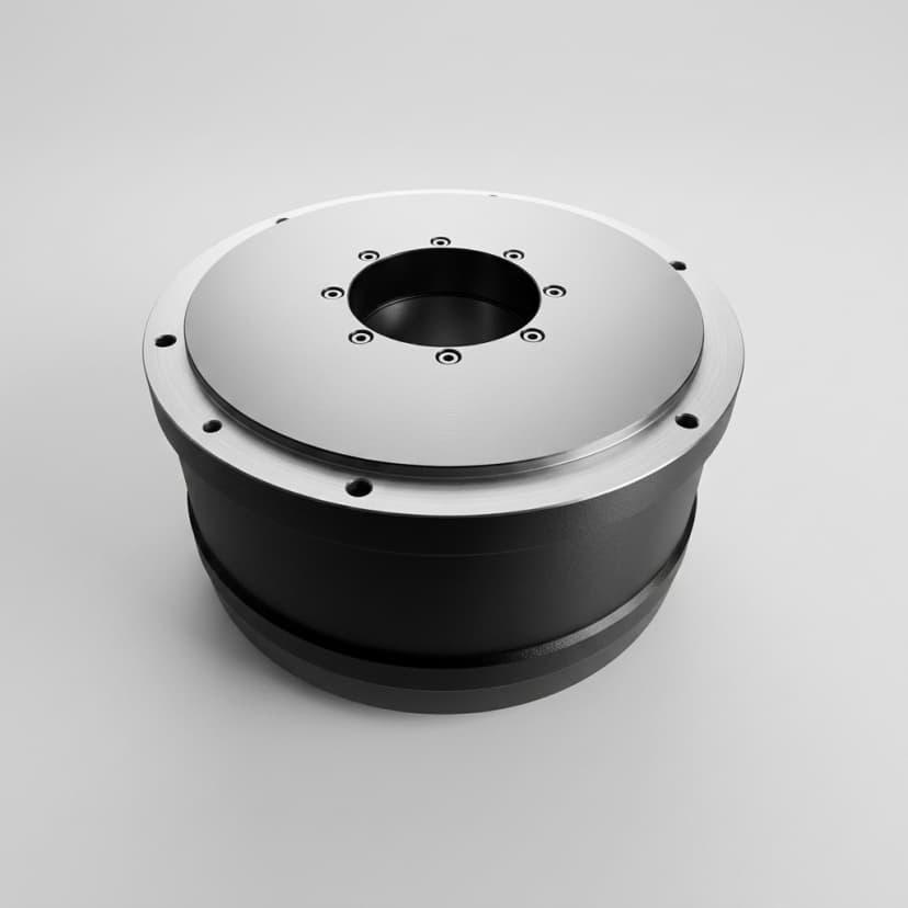
Outer-rotor high-torque robot joint actuator module for QDD applications

Key Takeaways

  • Torque control depends on mechanics, sensing, driver, and software together
  • Low reflected inertia and lower friction improve torque transparency
  • RFQs should include loop target, interface, and validation method

Where This Applies

  • Legged robot gait and contact control
  • Humanoid balance and compliant motion
  • Research robots validating torque loops

Engineering Focus

  • Current loop bandwidth and torque constant confidence
  • Encoder resolution, velocity estimation, and bus latency
  • Friction, ratio, reflected inertia, and thermal current limits

Engineering Decision Summary

A buyer should leave this note with a testable decision framework: which variables matter, what evidence is missing, and whether the actuator should move into sample selection.

Best Evidence

Start with control bandwidth and connect it to the real robot duty cycle instead of reviewing catalog values alone.

Primary Risk

Torque-control performance is inferred from motor torque only

Next Buyer Action

Prepare control mode and target loop bandwidth plus validation targets before requesting samples or commercial terms.
How to Use This Engineering Note

Engineering notes should help a buyer make a practical decision, not only define terminology. Use the criteria below to convert the concept into a sample-review plan.

Control bandwidth

Current loop 10–40 kHz, position loop 1–10 kHz, bus update 1–4 ms

Determines how quickly the joint can respond to contact and command changes.

Torque transparency

<5% torque ripple at 1 rad/s, friction compensation within 0.1 Nm

Defines how closely motor-side data reflects output-joint behavior.

Evidence to Collect During Review

The note is most useful when the buyer turns the concept into measurable checks during prototype review.

Signal to CheckReview BasisEvidence to Ask For
Control bandwidthCurrent loop 10–40 kHz, position loop 1–10 kHz, bus update 1–4 msReview driver current loop, encoder, gear ratio, friction, thermal limits, and bus timing together.
Torque transparency<5% torque ripple at 1 rad/s, friction compensation within 0.1 NmReview driver current loop, encoder, gear ratio, friction, thermal limits, and bus timing together.

Acceptance Thresholds to Define

Define measurable pass/fail thresholds before the sample arrives. This prevents a subjective review where one team checks torque, another checks packaging, and nobody records whether the actuator can move toward pilot build.

  • Control bandwidth: Determines how quickly the joint can respond to contact and command changes.
  • Torque transparency: Defines how closely motor-side data reflects output-joint behavior.

Where This Guidance Has Limits

The guidance is a selection framework. Final actuator fit still depends on the complete robot system, controller, and validation result.

  • Torque-control performance is inferred from motor torque only: Review driver current loop, encoder, gear ratio, friction, thermal limits, and bus timing together.

Data That Makes the Review Actionable

When sending an engineering question, include enough context for the supplier to answer with constraints and next tests instead of a generic definition.

Fixed Constraints

  • Control mode and target loop bandwidth
  • Required current/torque feedback fields
  • Encoder, bus, and controller architecture

Review Targets

  • Thermal duty cycle and current limit
  • Validation method for torque response

Engineering Image References

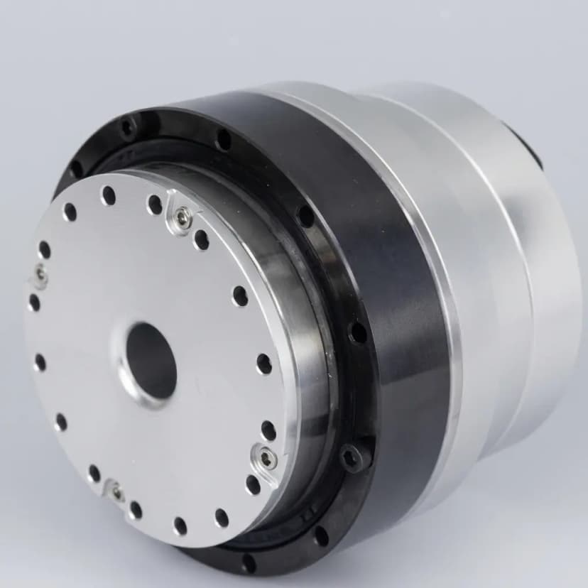
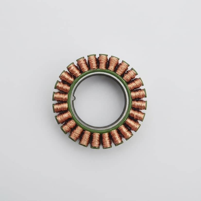
Product photos are used here as architecture references for buyer-side discussion. Final actuator selection depends on the validated joint envelope, ratio, torque-speed duty, and interface requirements.

Brushless robot joint actuator module for compact high-torque robot joint integration
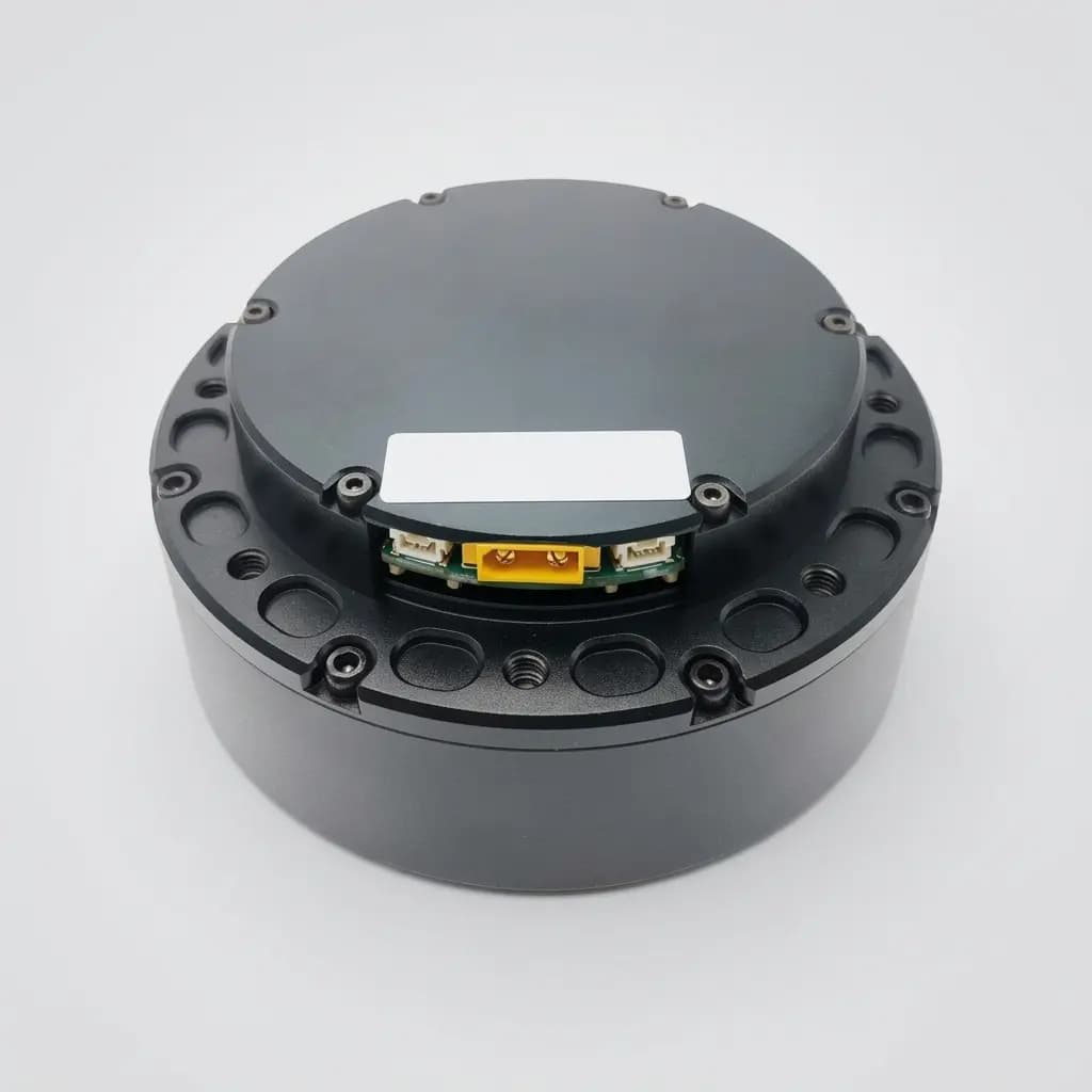
Outer-rotor brushless torque module for robot joint actuator comparison
Direct-drive motor reference for torque-control architecture discussion

Selection Criteria

CriterionTypical ReviewWhy It Matters
Control bandwidthCurrent loop 10–40 kHz, position loop 1–10 kHz, bus update 1–4 msDetermines how quickly the joint can respond to contact and command changes.
Torque transparency<5% torque ripple at 1 rad/s, friction compensation within 0.1 NmDefines how closely motor-side data reflects output-joint behavior.

Sample Review Inputs

  1. Control mode and target loop bandwidth
  2. Required current/torque feedback fields
  3. Encoder, bus, and controller architecture
  4. Thermal duty cycle and current limit
  5. Validation method for torque response

Risk Controls

  • Torque-control performance is inferred from motor torque only: Review driver current loop, encoder, gear ratio, friction, thermal limits, and bus timing together.

Buyer FAQ

Does QDD guarantee torque control?

No. QDD helps the mechanical side, but torque control still depends on sensing, driver quality, controller tuning, and validation.

Related Resources

Inquiry Email

[email protected]

Include robot type, joint location, torque/speed/voltage targets, quantity, and destination.

Instant Chat

+86 18857971991

Send QDD actuator specs, STEP files, or actuator references for engineering review.