LogoQDD Actuator
Start inquiry
LogoQDD Actuator
WhatsApp
LogoQDD Actuator

Shenzhen and Dongguan QDD actuator factory network supporting robot joint selection, prototype validation, sample review, and B2B export delivery.

Inquiry Email

[email protected]

Email app

Include robot type, joint location, torque/speed/voltage targets, quantity, and destination.

Instant Chat

+86 18857971991

Chat on WhatsApp

Send QDD actuator specs, STEP files, or actuator references for engineering review.

Products
  • QDD Robot Actuators
  • Backdrivable Actuators
  • Hollow-Shaft QDD Actuators
  • All Products
Solutions
  • Quadruped Robots
  • Humanoid Lower Limbs
  • Exoskeletons
  • All Applications
OEM Capabilities
  • Custom QDD Actuator
  • Prototype to Production
  • Private-Label Actuators
  • OEM Hub
Engineering
  • QDD Explained
  • QDD vs Harmonic Drive
  • Thermal Sizing
  • All Engineering Resources
  • QDD Actuator Blog
  • Buyer Resources
Resources
  • CAD / Datasheet Library
  • Developer Support
  • Compliance Documents
  • About
  • Manufacturing Network
  • Contact / RFQ
  • Privacy Policy
  • Cookie Policy
  • Terms of Service
© 2026 QDD Actuator. All Rights Reserved.|Direct QDD actuator RFQ: [email protected] | WhatsApp +86 18857971991 | LinkedIn contact.
Backed by Linkup Ai Co., Ltd. Manufacturing delivered by the Advanced Manufacturing Division of Linkup Precision.|Legal entity: Linkup Ai Co., Ltd.
Engineering & Dynamic Analysis

Quasi-Direct-Drive Motor

Quasi-direct-drive (QDD) motor sizing guidance for integrated modules, including 105Nm target configurations and 105nm integrated quasi-direct drive motor module selection.

Hybrid SpecCovers 105Nm integrated QDD motor module screening scope.
Use Sizing Tool Request RFQ
1. Selection Tool2. Assembly CAD3. Torque-Speed Envelope4. Reflected Inertia5. FOC & Encoders6. Bus & Latency7. Gearbox Efficiency8. Thermal & Safety9. Torque Drift10. Validation11. Tech Comparisons12. FAQ & Sources

QDD Joint Selection & Load Matching

Adjust target joint requirements below to estimate reflected inertia, gear ratios, and matched actuator models.

1. Input Target Joint Envelope

Robot Joint Application
105 Nm
10 Nm105 Nm (Target)350 Nm
150 RPM
50 RPM200 RPM450 RPM

2. Output Analysis✓ Ready

Recommended Ratio9:1Planetary Stage
Reflected Inertia0.0486 kg·m²J_rotor × N²
Est. Backdrive Torque< 0.51 NmHigh Backdrivability
Motor Torque & Speed12.96 Nm @ 1350 RPMBefore planetary losses
■ Calculations Log:
    Matched Module:QDD-105-9
    Request QDD-105-9 Specs

    105Nm QDD Actuator Cross-Section & CAD Reference

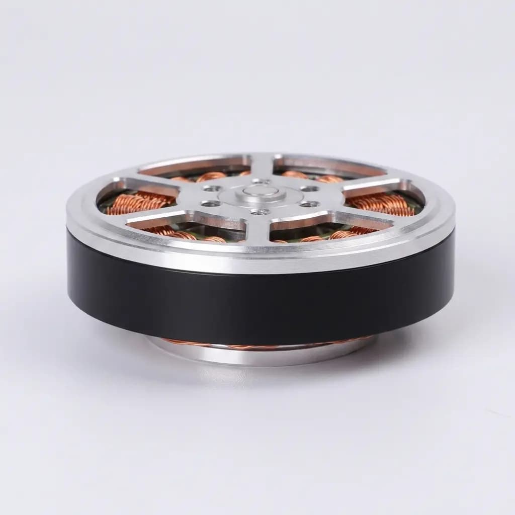
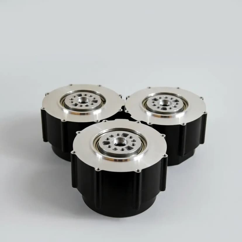
    The 105nm integrated quasi-direct drive motor module features a lightweight 9:1 planetary reducer nested within the rotor core. This design optimizes coaxial space and heat dissipation.

    • Integrated BLDC Stator
    • Sun Gear on Rotor Shaft
    • Dual 19-bit Encoders
    • Solid Planetary Carrier

    Target Dynamic Winding Specs:

    Peak Torque105 Nm
    Continuous35 Nm
    Total Mass2.45 kg
    Al-Alloy Outer Case (Flange)BLDC Stator Coils (48V)Rotor Neodymium MagnetsSUNPLANETPLANET9:1 Ring GearAbsolute EncoderOutput

    Table 1: QDD Actuator Family Specifications Matrix

    Model ClassPeak TorqueReduction RatioModule WeightContinuous TorqueTarget Joint Application
    QDD-24-624 Nm6:10.9 kg8 NmLight quadruped knee / Wearable joint
    QDD-60-860 Nm8:11.6 kg20 NmMedium quadruped knee / Humanoid arm
    QDD-105-9 (Target)105 Nm9:12.45 kg35 Nm105Nm Heavy quadruped hip-knee / Humanoid leg
    QDD-200-10200 Nm10:14.8 kg65 NmHeavy humanoid biped leg / Exoskeleton waist
    QDD-300-10300 Nm10:17.2 kg95 NmIndustrial legged transport robot joints

    Torque-Speed Envelope & Voltage Characteristics

    Operating voltage directly determines the back-electromotive force (Back-EMF) saturation point of the motor windings. Running the 105Nm QDD module at 24V limits its peak speed severely due to early voltage saturation.

    To output the target 105Nm peak torque at high gait speeds (e.g., 180 RPM knee extension), a 48VDC supply is optimal. Under 72VDC overdrive, the module can achieve an envelope extension up to 260 RPM before torque drop-off.

    Table 2: Voltage Supply vs Output Capability

    Bus VoltagePeak SpeedBack-EMF ConstantPeak Power Draw
    24 VDC90 RPM (Voltage Saturation)0.081 V/rad/s950 W
    48 VDC (Std)180 RPM (Optimal Winding)0.081 V/rad/s1,980 W
    72 VDC260 RPM (Overdrive Dynamic)0.081 V/rad/s2,850 W
    48V Target Winding24V Saturation LimitSpeed (RPM)
    QDD Zone (9:1)Harmonic (50:1)Gear Ratio

    Reflected Rotor Inertia & Shock Mitigation

    Reflected inertia ($J_{reflected} = J_{rotor} \times N^2$) dictates the mechanical impedance of the robot joint during impact. With high gear ratios, reflected inertia shoots up quadratically, causing high impact shear stress that can shear gear teeth.

    The 9:1 QDD configuration filters high-frequency external shocks by backdriving easily, allowing energy to propagate back to the motor winding. This makes QDD modules highly robust against hard landing collisions.

    Table 4: Reducer Architecture Trade-offs

    TypeBacklashBackdrivabilityShock Resistance
    Planetary (QDD)3–6 arcminHigh (<0.8 Nm)Excellent (Backdrives)
    Harmonic Drive<0.5 arcminNon-BackdrivableFragile (Shearing)
    SEA (Series Elastic)N/A (Soft)Compliance backdriveHigh (Elastic absorb)

    FOC Cascade Control Loop & Dual Encoder Feedback

    To eliminate the backlash error of the planetary gear stage, the module implements a dual-absolute encoder setup. The motor-side encoder (19-bit) tracks rotor position for the FOC current loop, while the load-side encoder (19-bit) measures output joint angles.

    Cascade PID loops run at 20 kHz for current, 2 kHz for speed, and 1 kHz for position. Dual-loop feedback compensates for non-linear transmission error, guaranteeing high mechanical accuracy.

    Table 5: Sensor Configuration Performance

    SetupBacklash Comp.BandwidthComplexity
    Single EncoderNo CompensationHighLow
    Dual Encoder (Std)Yes (Software LUT)Medium-HighMedium
    Encoder + Torque SensorDynamic Torque ForceLow-MediumHigh
    Pos LoopVel LoopFOC CurrentBLDC MotorPlanetary19-bit Motor Enc19-bit Load Enc (Backlash Comp)

    Integrated Driver Bus Communication & Control Latency

    In dynamic legged robotics, force control loop bandwidth is highly restricted by communication bus latency. Delays in position/torque commands propagate into phase delays, causing joint instability or violent oscillations during high-frequency impact events (e.g., foot landing).

    The 105Nm QDD module integrates an industrial-grade EtherCAT controller (CoE profile) supporting Distributed Clocks (DC) with jitter <2μs. This enables hard real-time synchronization, pushing torque command bandwidth to 2.0 kHz.

    Table 8: Bus Communication Protocols Comparison

    ProtocolTypical LatencyClock JitterTorque BandwidthFail-Safe Capability
    EtherCAT (CoE)0.1–0.5 ms±2 μs (Dist. Clock)Up to 2.0 kHzExcellent (Ring Redundancy)
    CAN-FD0.8–1.5 ms±25 μsUp to 1.0 kHzHigh (Arbitration/CRC)
    RS-485 (RTU)2.5–5.0 ms±150 μsUp to 200 HzMedium (Half-duplex packet loss)
    Master PCNode 1: HipNode 2: KneeEtherCAT RingNode 3: AnkleLatency < 0.5 ms
    Friction Loss IncreaseIdeal Backdrivable LineOutput Load (Nm)Mechanical Efficiency (%)

    Planetary Reducer Mechanical Efficiency & Backdrive Math Modeling

    Planetary transmission efficiency ($\eta$) is not a fixed constant. It varies dynamically based on rotor speed, joint output torque load, and operating temperature. In low-torque, high-speed regimes, grease shearing dominates losses, reducing efficiency to ~86%.

    The mathematical relationship for joint backdrivability determines the minimum torque ($T_{backdrive}$) required on the output shaft to spin the motor rotor backward:T_backdrive = (T_friction_motor * N) / η + T_friction_gearUsing a single-stage 9:1 planetary reducer allows $T_{backdrive}$ to stay under 0.8 Nm, yielding outstanding joint transparency.

    Table 9: Reducer Efficiency vs Working Regimes

    Load CaseEfficiency (η)Lubricant Temp.Dominant Loss Factor
    Nominal Load (35 Nm, 120 RPM)91.2%55°C (Stabilized)Optimal lubrication viscosity
    Low Load / High Speed (10 Nm, 240 RPM)86.5%40°CFluid shear dragging loss
    Peak Impact Load (105 Nm, 30 RPM)83.8%85°C (Transient peak)Elastohydrodynamic film compression
    Safe: 25-100°C4%/°C DeratingTemp (°C)

    Active Thermal Protection & Derating Limits

    Continuous operating torque is restricted by copper winding losses ($I^2R$). Winding temperatures above 110°C will trigger active current limits to prevent thermal breakdown of winding insulation.

    When winding temperatures cross 100°C, the FOC driver applies a 4%/°C linear derating curve, shutting down completely at 125°C.

    Table 3: Dynamic Winding Thermal Limits

    Gait Load CaseRMS TorqueTemp RiseMax Duration
    Static Standby12 Nm<0.05°C/sInfinite
    Slow Gait / Walk35 Nm~0.25°C/s240 seconds (to 100°C)
    Trot / Jump landing105 Nm~1.40°C/s4.5 seconds (Pulse burst)
    WindingConvectionHousing fins

    Integrated Dissipation and Frame Heat sinking

    Standard modules utilize radial thermal fins machined directly into the Al7075 housing. Mounting the module on an aluminum robot frame piece (acting as a heat sink with surface area >0.05m²) increases passive dissipation by 150%, delaying active current limits indefinitely under walking gait RMS profiles.

    Torque Estimation Error & Winding Temperature Calibration

    Without a load-side torque sensor, joint torque is estimated via motor phase current. However, magnetic flux linkage ($\Psi_m$) and copper winding resistance drift as temperatures rise, causing torque estimation errors up to 8.5% at 110°C.

    The internal FOC firmware contains a temperature look-up table (LUT) that compensates for magnet flux degradation. Dynamic temperature compensation keeps torque estimation error below ±1.2%.

    Table 7: Factory Calibration Standards

    Calibration TestTolerance LimitMethods
    Gear Backlash Drift< 4.5 arcminReverse locking dyno torque cycle
    Torque Ripple (Friction)< 1.5% of peakPhase current mapping compensation
    Thermal Estimator drift±1.2% accuracyPT1000 sensor feedback LUT sweep
    Uncompensated Drift (~8.5%)LUT Compensated (±1.2%)Winding Temp (°C)
    θ_motorθ_load × NError LUT Correction

    Online Mechanical Calibration LUT

    Every QDD module goes through factory calibration to map the difference between the motor rotor and load shaft angles across 360° rotation. Non-linearities from planetary gear backlash and structural elasticity are stored in a lookup table (LUT) inside the driver EEPROM to compensate dynamically for joint positioning errors.

    Application Validation Scenarios

    How to use the 105Nm QDD motor module target class as an RFQ and sample-test screen before treating it as a validated robot joint.

    175kg biped landing screen (knee joint)

    Premise: Humanoid robot (75kg) executing a 0.4m vertical jump and landing. The knee joint requires peak torque of 100 Nm and quick shock energy absorption.

    Process: Use the QDD-105-9 target class at 48V as an RFQ screen, then request supplier landing-pulse dyno logs, bus-clamp sizing, and gearbox inspection criteria before committing the knee architecture.

    Result: Decision output: 105 Nm peak torque is plausible for first-pass packaging, but release requires signed impact-cycle data and post-test backlash inspection on the final joint stack.

    245kg quadruped endurance screen (hip/knee joint)

    Premise: Quadruped inspection robot walking on gravel road under 40°C ambient temperatures for 24 hours continuously. Knee joints RMS torque is 28 Nm.

    Process: Evaluate the QDD-105-9 target class against mounted-frame thermal assumptions, then request supplier RMS-duty thermal curves instead of relying on open-air peak-torque ratings.

    Result: Decision output: proceed only if the supplier provides winding-temperature logs for the intended mounting path, ambient temperature, current limit, and gait duty cycle.

    3Wearable rehabilitation exoskeleton screen

    Premise: Rehabilitation active exoskeleton for patients. Active compliance (low mechanical impedance) is required, limiting hand-driven backdrive torque to < 0.8 Nm.

    Process: Compare a lighter QDD-60-8 class with the 105 Nm class because patient-worn joints often care more about backdrive torque, mass, and unpowered safety than peak torque.

    Result: Decision output: if hand-backdrive torque and mass dominate the requirement, do not overspec a 105 Nm integrated module without a brake, fail-safe, and comfort review.

    4Collaborative robot arm force-control screen

    Premise: Collaborative arm handling 5kg payload. Fast collision detection (<15ms) is needed for human safety compliance under ISO TS 15066.

    Process: Screen QDD-105-9 modules for base and shoulder axes only after comparing reducer stiffness, current-estimated torque resolution, and whether an external torque sensor is required.

    Result: Decision output: use current-estimated torque for early prototypes, but request safety validation, sensor evidence, and controller logs before collaborative deployment.

    Structure Material & Transmission Comparison

    How the structural casing materials perform under dynamic loads and heat dissipation needs.

    Table 6: Housing structural Material Selection

    Material GradeTensile YieldDensityThermal Cond.
    Al7075-T6 (Standard)503 MPa2.81 g/cm³130 W/m·K (Best cooling)
    Ti-6Al-4V (Titanium Gr5)880 MPa4.43 g/cm³6.7 W/m·K (Poor thermal)
    CFRP (Carbon Fiber)~600 MPa (Anisotropic)1.55 g/cm³< 5.0 W/m·K (Needs sinks)

    Planetary Gear Contact Stress Concentration

    Angle (22.5°)

    Pressure angle increased to 22.5° to withstand peak torque shear forces.

    Buyer FAQ for 105Nm Integrated QDD Modules

    These questions match the page structured data and cover the alias-search intent before a technical RFQ.

    What is a 105nm integrated quasi-direct drive motor module?

    It is a highly integrated robotic joint module concept that packs a high-torque brushless PMSM motor, a low-ratio planetary gear such as 8:1 or 9:1, high-resolution absolute encoders, and thermal sensors into a compact housing. A 105 Nm peak-torque class can fit quadruped knees or humanoid hip/knee screening, but the final rating must be confirmed with supplier datasheets, duty-cycle curves, and sample validation.

    Why choose QDD motors over harmonic drive actuators?

    QDD motors trade off some positional holding stiffness for backdrivability, high impact robustness, and transparency in torque control. Harmonic drives have high ratios, are non-backdrivable, and can easily shear under external impact, whereas QDD gear teeth are robust and the output can easily reverse-drive the motor to dissipate impact energy.

    What are the customization options for integrated motor modules?

    We support customizing motor windings for different bus voltages (e.g., 24V, 48V, 72V), customizing output shaft and flange geometry, absolute encoder options (BiSS-C, SSI, Incremental), integrated brake configurations, and different communication protocols (EtherCAT, CAN-FD, RS485).

    Related QDD Motor Module Paths

    Use these pages to move from 105Nm integrated module screening into product comparison, thermal validation, and supplier-confirmed RFQ inputs.

    105Nm quasi-direct-drive actuator product pageCompare packaged 105 Nm actuator specifications before RFQ.Backdrivable actuator selectionReview when low impedance and contact safety are the priority.Low-ratio planetary actuator optionsCheck ratio, reflected inertia, and packaging trade-offs.QDD vs harmonic-drive jointsCompare backdrivability, stiffness, impact behavior, and backlash.Thermal sizing for QDD jointsValidate continuous torque and duty-cycle limits.Custom QDD actuator OEM pathMove from screening assumptions to supplier-confirmed drawings.

    Technical FAQ

    Why is reflected inertia a critical safety metric for humanoids?

    Reflected inertia is calculated by multiplying the motor rotor inertia by the square of the gear ratio. In traditional high-ratio harmonic systems, a 100:1 ratio multiplies rotor inertia by 10,000. Under high-speed collisions, this inertia causes high destructive forces before the controller can react. In a 9:1 QDD system, the multiplier is only 81, allowing the output shaft to rotate backward and safely absorb impact.

    What gear tooth profile is optimized for the 105Nm planetary carrier?

    We utilize gear teeth profile modification with a pressure angle increased to 22.5°. This design increases tooth root thickness, shifting stress concentration away from the pitch circle and doubling bending fatigue strength under jump landing shocks.

    How do you solve planetary backlash deterioration over long-term robot operation?

    By implementing eccentric planetary pin preloading and hard carburizing treatment on gear surfaces. This minimizes tooth wear, ensuring the backlash degradation is under 2 arcmin after 10,000 hours of standard walk gait cycles.

    Is the hollow shaft diameter customizable for specific routing needs?

    The standard 105Nm module has a 15mm clear inner bore. We can customize the through-hole diameter up to 22mm, but this reduces output bearings housing space. Contact sales to check load ratings.

    What is the primary factor limiting the lifespan of a QDD planetary reducer?

    Planetary needle bearing contact fatigue. Due to low ratio rotation, grease can be squeezed out of bearing channels. We use high-pressure polyurea grease to maintain grease coverage and extend L10 life.

    What is the difference between direct drive (DD) and quasi-direct drive (QDD)?

    DD has no gear stages, leaving it torque-limited for humanoid knees. QDD uses 6:1 to 10:1 reducers to multiply motor torque while preserving backdrivability, low weight, and high torque transparency.

    RFQ Specifications Checklist

    Include these parameters in your inquiry to accelerate quotation and engineering review:

    • 1.Joint configuration, peak dynamic loading, and gait trajectory details
    • 2.Target torque class (e.g., 105Nm peak) and motor input voltage (24V–48V)
    • 3.Interface mechanical dimensions (flange, shaft type) or STEP models
    • 4.Encoder type, absolute feedback requirement, and brake options
    • 5.Expected prototype count, annual volume, and required certification (CE/RoHS)

    Technical Reference Sources & Evidence Boundaries

    Evidence reviewed on July 28, 2026. Use this page as an engineering screening model for a 105nm integrated quasi-direct drive motor module, not as a final signed datasheet. Public sources support the QDD architecture and comparison logic; supplier-specific 105 Nm limits still need project-level validation.

    Source Links

    • Partial-assist knee orthosis QDD actuator

      Peer-reviewed reference for low-ratio QDD actuation, compact backdrivable knee assistance, torque, temperature, and validation framing.

    • Open-source QDD actuators for legged locomotion

      Research context for QDD actuator design, characterization, Joule heating, continuous torque limits, and legged-robot duty cycles.

    • Motor selection metrics for QDD actuators

      Research basis for balancing motor torque, inertia, motor constants, and transmission ratio in quasi-direct-drive systems.

    • CubeMars QDD motor catalog

      Commercial QDD category reference for comparing public product classes; verify final figures against current supplier datasheets.

    • Unitree H1 humanoid reference

      Commercial humanoid platform reference for joint-level load context; not a substitute for component-level supplier drawings.

    • maxon HEJ integrated joint product line

      Commercial integrated-joint reference for torque-density benchmarking and RFQ comparison boundaries.

    Known / Unknown Boundary

    Evidence ClassDecision Boundary
    Public evidence supportsLow-ratio QDD architecture, reflected-inertia tradeoffs, backdrivable actuator validation methods, and thermal/duty-cycle concerns.
    This page modelsA 105 Nm target class using transparent assumptions for ratio, efficiency, bus voltage, torque demand, and speed demand.
    Supplier must confirmPeak and continuous torque, torque-speed curves, mounting heat path, backlash, impact-cycle data, firmware limits, and safety behavior.
    Do not inferThat scenario outputs are published field-test guarantees or that one 105Nm module fits every humanoid, quadruped, arm, or exoskeleton joint.
    Treat all tables above as screening ranges unless a supplier provides signed torque-speed curves, thermal logs, inspection limits, controller firmware notes, and sample-test results for the same mounting and duty cycle.
    Classification: Open Engineering Screening ReferenceEvidence Reviewed: July 28, 2026

    Request 105Nm QDD Motor Module Quote

    Contact our applications team to discuss your joint envelope, target ratios, loading cycles, and batch delivery schedules.

    Inquiry Email

    [email protected]

    Email app

    Include robot type, joint location, torque/speed/voltage targets, quantity, and destination.

    Instant Chat

    +86 18857971991

    Chat on WhatsApp

    Send QDD actuator specs, STEP files, or actuator references for engineering review.