
QDD actuator thermal management
Thermal Management in QDD Actuators: Navigating Continuous vs. Peak Torque Specs
Peak torque sells actuators, but continuous torque decides whether a QDD robot joint survives a real duty cycle. This guide separates burst ratings from thermal limits and gives buyers the RFQ evidence to request before sample approval.

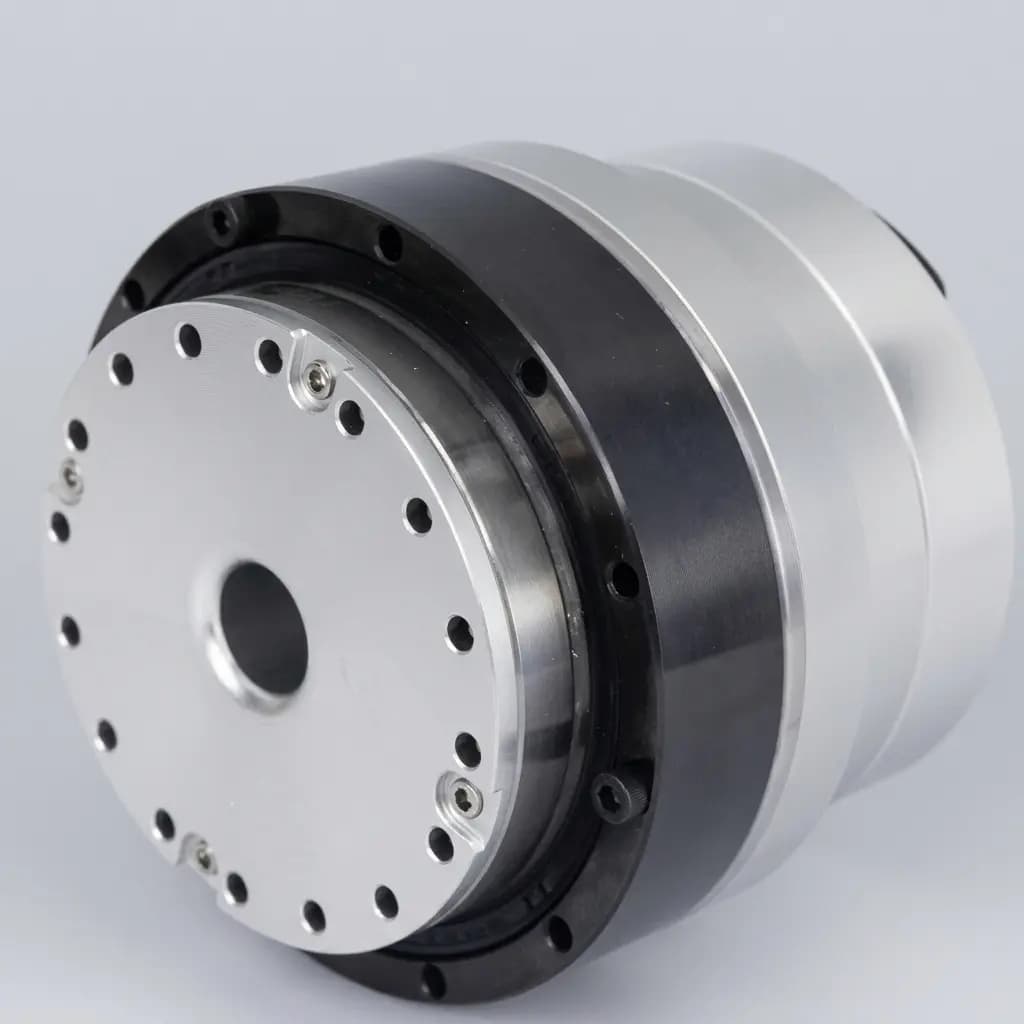
Product References for This Article
These images are included to make the engineering discussion more concrete. Use them as visual references for actuator envelope, output interface, routing, and architecture trade-offs before requesting exact drawings or datasheets.
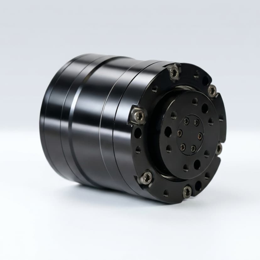
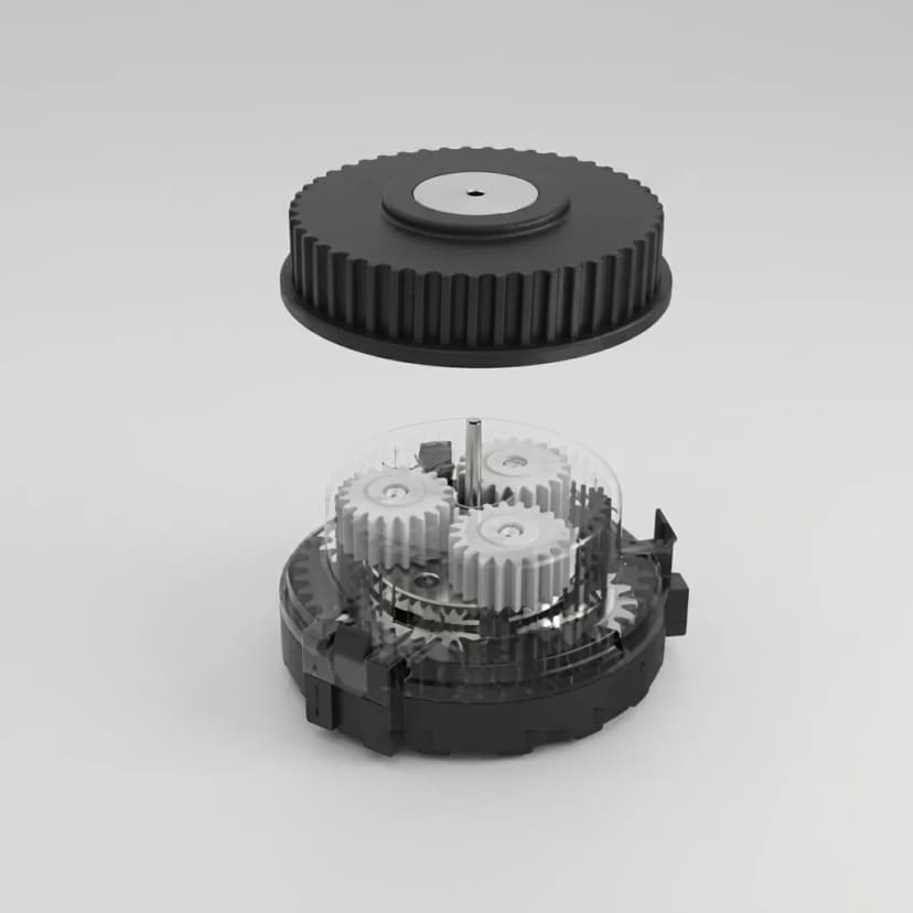
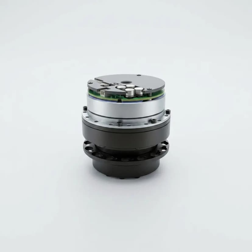
Thermal limit, not peak torque, controls usable QDD sizing
Quasi-direct-drive actuators use low-ratio gear reduction to preserve backdrivability, impact tolerance, and force-control feel. The trade-off is that the motor must supply more raw electromagnetic torque than a high-ratio joint, so current and copper loss become central sizing constraints.
Copper loss follows P_loss = I²R. A modest increase in holding torque can create a much larger heat rise, especially when a quadruped knee, humanoid ankle, cobot elbow, or exoskeleton joint spends time producing static or low-speed torque. This is why continuous torque should be compared at thermal equilibrium, not inferred from a short burst rating.
Thermal management architecture comparison
| Cooling path | What to verify | Selection trade-off |
|---|---|---|
| Passive aluminum housing | Ambient temperature, mounting plate, and free-air thermal soak | Lowest cost and easiest sealing, but the smallest continuous-torque margin |
| Finned housing | Fin exposure, dust loading, and airflow around the robot joint | Useful passive improvement, but increases joint diameter and cleaning burden |
| Forced air | Fan life, acoustic limit, ingress protection, and blocked-flow behavior | Strong continuous-torque gain in clean indoor systems, weaker fit for dusty field robots |
| Chassis conduction | Thermal pad/paste stack, bolt preload, and limb-section heat capacity | High value when the robot frame can act as a heat sink, but validation must use the real chassis |
| Liquid cooling | Pump, radiator, leak path, coolant temperature, and service plan | Highest thermal headroom, but adds complexity, mass, failure modes, and maintenance |
| Heat pipe or phase-change path | Orientation sensitivity, radiator contact, and supplier process capability | Can move heat efficiently without a pump, but usually needs custom engineering |
Peak torque is a burst rating; continuous torque is a thermal test
Peak torque usually describes a short burst limited by current, magnetic saturation, driver capacity, or mechanical strength. It is useful for jump recovery, impact response, or short acceleration events, but it should not be used as the walking, holding, or payload-carrying rating.
Continuous torque needs a complete test condition: ambient temperature, sensor location, airflow, housing or heat-sink attachment, controller current limit, and the temperature threshold used for throttling. Without those conditions, two identical-looking catalog numbers may describe very different real actuator capacity.
Supplier evidence to request before sample approval
- Thermal resistance from winding to housing and housing to ambient or chassis.
- Continuous torque curve with ambient temperature, mounting condition, and sensor location stated.
- Peak torque duration, cool-down interval, and allowed duty cycle at the quoted voltage and current limit.
- Thermistor or temperature-sensor placement plus the controller throttle and shutdown thresholds.
- Magnet temperature grade, winding insulation class, and maximum allowed stator or winding temperature.
- Thermal-soak logs from a load case close to your gait, hold, lift, or repeated manipulation duty.
Scope and limits for 2026 sourcing
Use this article as a Global, English-language screen for RFQ preparation. It does not replace supplier datasheets, signed validation reports, or your own thermal tests on the final robot chassis.
The safest procurement rule is to size around RMS or steady-state torque, then treat peak torque as a transient reserve. If a supplier quotes only a large burst number, ask for the missing duty-cycle and thermal-equilibrium data before committing the mechanical design.
Selection Metrics
| Metric | Review Range | Why It Matters |
|---|---|---|
| Continuous torque test condition | Defined by supplier test setup | Continuous torque is only comparable when ambient temperature, mounting, airflow, and sensor location are stated. |
| Peak torque duration | Often seconds, not minutes | Burst torque helps with jumps and impacts, but it cannot define walking, holding, or payload capacity alone. |
| Thermal resistance | Winding-to-housing and housing-to-ambient or chassis | Thermal resistance lets engineers estimate winding temperature rise from copper and driver losses. |
| RMS torque over duty cycle | Application-defined | RMS torque is usually a better predictor of heat rise than the highest instantaneous torque command. |
| Temperature telemetry path | NTC/PTC or digital sensor near winding, stator, or driver | A sensor in the wrong location may delay throttling and hide winding or magnet hot spots. |
| Cooling architecture | Passive, finned, forced air, chassis conduction, liquid, or heat pipe | Cooling choice changes continuous torque margin, sealing, field reliability, and service burden. |
RFQ Checklist
- Robot type, joint location, payload, linkage geometry, and expected ambient temperature
- Continuous torque, peak torque, speed, voltage, current limit, and RMS duty-cycle target
- Thermal mounting condition: free air, bolted chassis, finned housing, forced air, or liquid loop
- Allowed winding, stator, magnet, driver, and housing temperature limits
- Temperature sensor location, telemetry access, throttle behavior, and shutdown threshold
- Required evidence: thermal-soak logs, torque-speed curves, duty-cycle chart, and sample test method
- Cooling or sealing constraints: IP rating, fan serviceability, liquid-cooling maintenance, and dust exposure
- Mechanical envelope, bolt pattern, output interface, cable exit, and heat-sink contact area
Related Pages
Buyer FAQ
Should we size a QDD actuator from peak torque?
No. Use peak torque for short transient events only. Walking, holding, lifting, and repeated manipulation should be sized from continuous or RMS torque under defined thermal conditions.
Why can two QDD actuators with the same peak torque behave differently?
Peak torque may be similar while stator size, copper fill, housing conduction, sensor placement, controller limits, and cooling path differ. Those details decide continuous torque and thermal trip behavior.
Is standing still hard on a QDD quadruped joint?
Yes. A bent-knee stance can require high holding current with little airflow, so copper loss accumulates even though the joint is barely moving.
When is liquid cooling justified?
Liquid cooling is justified when continuous duty is high, passive mass is constrained, and the program can accept pumps, radiators, leak risk, maintenance, and validation complexity.
What is the first thermal question procurement should ask?
Ask what continuous torque means in the supplier test: ambient temperature, mounting condition, airflow, current limit, sensor location, and shutdown or throttle threshold.
Sources & References
- CubeMars
Product-category and selection context for commercially available QDD actuators, frameless motors, and integrated joint modules.
- PulsarHRI
Supplier context for QDD actuator duty-cycle limits, motor/gearing trade-offs, and backdrivable humanoid/robotics use cases.
- Proprioceptive Actuation for Highly Dynamic Locomotion Systems
Research evidence on quasi-direct-drive actuator thermal behavior, liquid cooling, Joule heating, and continuous torque improvement.
Inquiry Email
Include robot type, joint location, torque/speed/voltage targets, quantity, and destination.
Instant Chat
+86 18857971991
Send QDD actuator specs, STEP files, or actuator references for engineering review.